
When working with laminates like plywood, especially high-end material like Baltic Birch plywood, I love using a compression end mills as they give the best cut finish on both the top and bottom surfaces of the material. It is important to understand how to properly setup your CAM program to get the best results with these types of end mills.
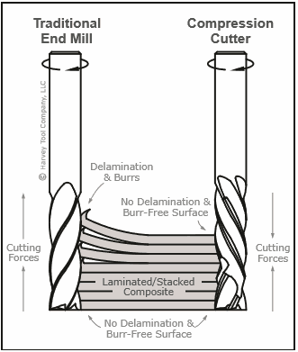 Before I get into the settings I wanted to take a second to explain what exactly a compression end mill is. The image to the right illustrates this. (photo credit: Engman-Taylor Company) Typically there are two common types of end mill spiral geometry, up-cut and down-cut. An up-cut will give you a great finish on the bottom side of your workpiece when you cut all the way through the material as it is designed to pull chips upward causing a sheering action on the bottom. However, this causes a very poor finish on the top surface as the laminates of the plywood splinter along the cut line. Additionally, an up-cut end mill can cause delamination to the inner part of the material as well. Conversely, you can use a down-cut end mill which will give you a very nice finish on the top of the material but will often cause splinters on the bottom of the material.
The solution for the best finish quality on laminated material is to use a compression end mill. A compression end mill has a up-cut flute geometry from the tip to usually about 1/3 of the cutter length at which point it converts into a down-cut flute. The advantage is that the end mill, when used properly, will give you a nice clean top and bottom finish on your work piece.
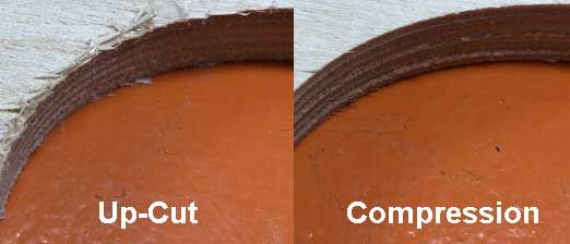
In order to get the best finish using a compression bit, it is important that your first pass goes deep enough into your material so the down-cut spiral is engaging with the top surface of the material. This dimension is usually indicated by the manufacturer, however if it is not, you can always measure it with a pair of digital calipers. If you do not plunge the bit past the spiral change then it will act the same as an up-cut end mill and give you the same frayed finish (see example).
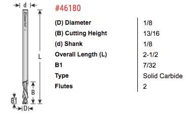
The bit that I am using for this project is an Amana Tool 46180 1/8"(.125") Compression Spiral. It has an overall length of 2 1/2" (2.5") and a total cutting height of 13/16" (.8125"). The spiral change (indicated by B1 in the illustration) happens at 7/32" (.21875"). So this tells me that I need to make sure my first pass depth is at least .21875", which I rounded up to .22". After that I keep the pass depths to 1/8" which is recommended by Amana.
Using Vectric Cut 2D or VCarve you can easily customize the pass depths by clicking on the EDIT PASSES button when setting up your tool paths.
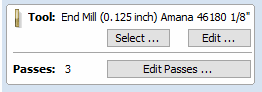
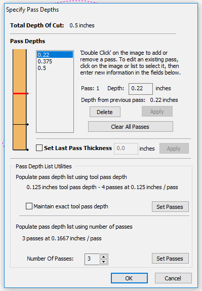 A window will pop up and it will allow you to make changes to each pass depth. If you set the end mill up for 1/8" pass depths in your tool library, then you will see 4 pass depths in box.
Click on the top pass depth, which should be .125" and you will see "Pass: 1 Depth" with a text box. In that box enter ".22". Since you are cutting .22" deep in the first pass, there is no reason to keep the .25" pass as the second, so you can simply click on that number and press the DELETE button.
You will now have 3 total passes: .22", .375" and .5". This is taking into consideration that my material measured .47" thick and I want my lass pass to be .030" deeper to ensure that I get a clean uniform cut. Remember that the first .21875" of the bit is an up-cut, so this will give me a nice clean bottom finish.
PLEASE NOTE: You MUST use a spoilboard any time you intend to cut deeper than the thickness of your material to avoid cutting into your machine's bed.
The next thing we need to do is to determine the best speeds and feeds for this end mill. Compression bits typically can not run as fast feed rates as you would with a traditional up-cut end mill. But that is okay because the additional time you spend when running the job is no where near as much time that you will spend sanding and manually cleaning up the work piece.
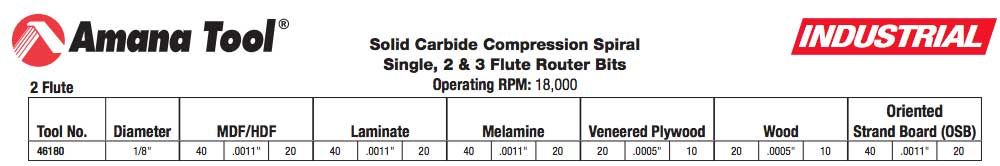
Most quality end mill manufacturers will give you speed and feed rates for each of their cutting bits. Amana Tool does a very good job at this including a downloadable PDF file for all of their end mills illustrating the proper settings for various types of material.
In the image below you can see their required settings for MDF/HDF, Laminate, Melamine, Veneered Plywood, Wood and Oriented Strand Board (OSB). For Baltic Birch Plywood we will concentrate on the Veneered Plywood column. You can see that they indicate the feed rate of 20 IPM (inches per minute) with a chip load of .0005". At the top of the document they indicate that the operating RPM should be 18,000. The chip load is based on a pass depth equal to the diameter of the end mill, so in this case .125".
I always like to run these numbers through a program called G-Code Wizard to verify my settings before I run on the machine. If you are interested in obtaining a copy of G-Code Wizard, please click HERE.
Here is what G-Code Wizard is telling me based on the parameters that I input for my cutting tool and machine.
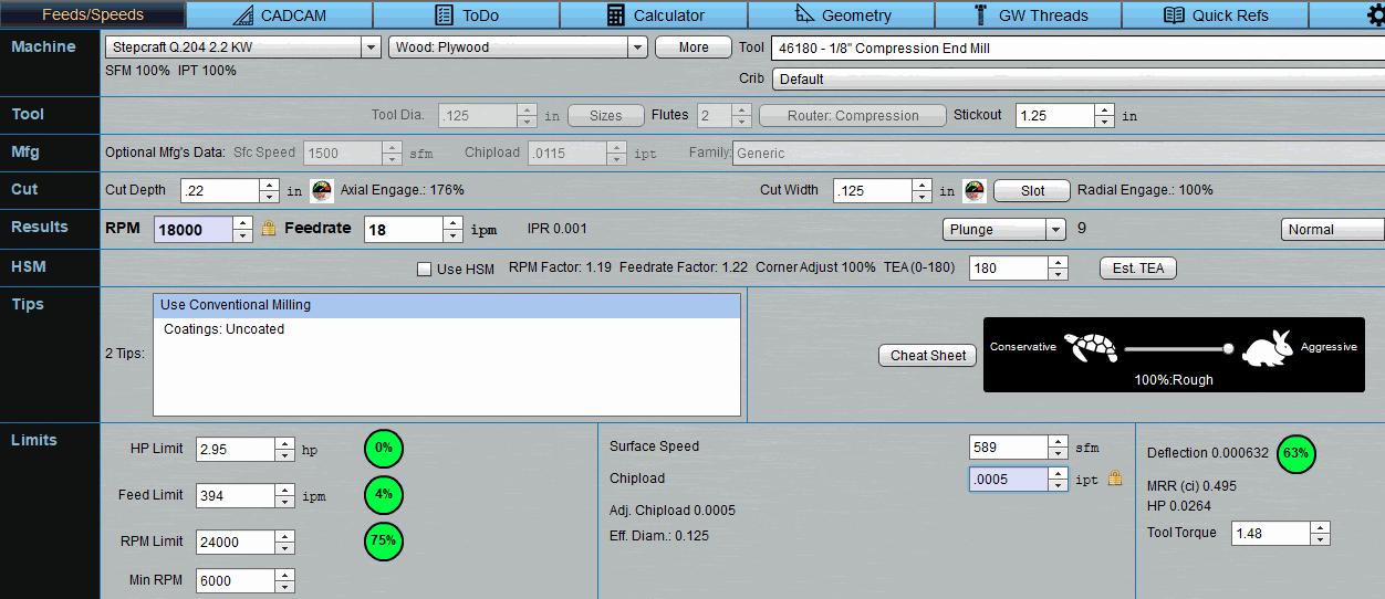
The first line (Machine), I selected my STEPCRAFT Q.204 CNC with a 2.2KW spindle. All of the parameters for this machine are already loaded into the software's library. On the same line, I selected my Amana 46180 from my tool crib.
Since I know that my worse case cut depth on this end mill was going to be .22" (my first pass so I can get past the spiral change), and then all other passes would be .125", I entered .22 into the cut depth box. I wanted to ensure I knew the worse case scenario so I would not over-stress this end mill.
In the Limits row, I setup my Chipload per the manufacturer's chart, which is .0005" and in the Results row, I locked my RPM to 18,000 per the manufacturer's suggestion . This gave me a resulting feed rate of 18 IPM, which is slightly slower than the chart. This is because we are basing this on the worse case pass depth of .22" and not the .125" which the chart was based on.
Some important things to notice on this screen which you always want to pay attention to are the HP Limit, Feed Limit, RPM limit, and Deflection. You want to make sure that you adjust your settings so these circles are always green.
HP Limit - is how much of the available spindle horsepower you are using with the settings that you have. In my case I am not really using any since it is such a small cutter which does not strain the spindle.
Feed Limit - is how much of the available machine feed speed that you are using. On the STEPCRAFT Q.204, it has a maximum rapid speed of 394 IPM of which I am only using 4%
RPM Limit - I am using the HFS-2200 spindle on the Q.204 which has a max RPM of 24,000. At 18,000 RPM for this project I am at 75% of the spindle's capacity.
Deflection - This indicates how much your end mill will deflect (or bend) using the current settings. If this number is 100% or greater then that circle will be red which indicates that you have a very good chance of snapping your bit using the settings provided. I am at 63% which is more than fine for this bit and job. I typically try to stay under 75% and will adjust other settings to get me to this range.
One other setting that G-Code Wizard gives you is what direction to run your tool path. In this case it is telling you to use a conventional tool path which you can easily set in Vectric or any other CAM program that you use.
If you are not using compression end mills, then you are missing out on a solution that takes the frustration out of cutting laminate material, MDF and Veneers. For more information, please email info@stepcraft.us.
The Correct Way To Setup A Compression End Mill